Summary
Learn how to model and analyze solar radiation in SOLIDWORKS Flow Simulation to optimize outdoor designs and thermal performance.
Solar Radiation in SOLIDWORKS Flow Simulation
When designing outdoor electronics, building facades, or any object exposed to the sun, solar radiation is a critical heat source that can dramatically change your product’s lifespan. Knowing how the sun’s power affects your design can help you make decisions that help produce a better end product.
SOLIDWORKS Flow Simulation offers a powerful yet often underutilized feature to model solar radiation and its impact on heat transfer.
 Solar radiation bouncing off a satellite dish
Different Types of Heat Radiation
Heat radiation from the computational domain far-field boundaries or the model openings can be defined as environmental or solar radiation in SOLIDWORKS Flow Simulation. These radiation types can be applied to both internal and external flow studies.
Environmental Radiation
Environmental radiation is the non-directional energy flux generated by the walls of an imaginary huge “room” that surrounds the body. This flux has predefined radiation parameters.
Solar Radiation
In contrast to the environment radiation, the solar radiation is modeled by the directional energy flux. Therefore, the solar radiation is defined via its power flow (intensity) and its directional vector. In addition to the solar radiation from the computational domain boundaries, a solar radiation source emitting directional radiation can be also specified.
How to Define Solar Radiation in SOLIDWORKS Flow Simulation
To enable solar radiation, you will have to enable Heat Transfer in the general settings of the project setup and then select Radiation.
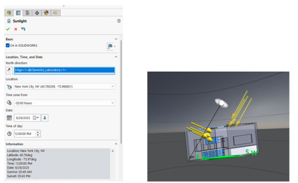 Defining solar radiation via sunlight
There are following ways you can define solar radiation in SOLIDWORKS Flow Simulation using either Discrete Transfer or Discrete Ordinates method:
- By Location, Time, and Turbidity
- Location can be selected from the pre-defined cities available in SOLIDWORKS Flow Simulation’s engineering database or by defining a custom city.
- Date can be defined from month, day, and time.
- Turbidity factor allows you to describe the optical thickness of the atmosphere due to the presence of water vapor or pollutants in the atmosphere.
- By Location and Time
- By Direction and Intensity
- A directional vector (X, Y, Z) components and intensity can be defined.
- By Azimuth and Altitude
- By Model Sunlight
- You can specify solar radiation boundary condition by linking it to the SOLIDWORKS Sunlight option, found in Camera Settings option.
Differences Between Discrete Transfer and Discrete Ordinate Models
The Discrete Transfer method is the default Radiation model available in SOLIDWORKS Flow Simulation. If you have the add-on HVAC module, you can enable Discrete Ordinate model for radiation calculation.
Discrete Transfer Model
The Discrete Transfer model is capable of simulating only diffusive reflection or 100% specular reflection if defined via radiative surface boundary condition of symmetry type. It cannot handle spectral dependencies. However, it can handle geometric optics with a directional source using a Forward Solar Ray tracing method instead of the default Backward Solar Ray tracing.
Discrete Ordinate Model
The Discrete Ordinate model available with the SOLIDWORKS Flow Simulation HVAC module is capable of handling spectral (wavelength) dependencies and supports the use of semi-transparent surfaces. For high temperature gradients and accounting of geometric-optical effects, the default Discrete Transfer method is recommended.
Example of Creating a Study for Solar Radiation
As an example, the Sunlight option can be used to set up solar radiation. The orientation, time, and duration are defined in the general study settings in SOLIDWORKS Flow Simulation and can be time-dependent.
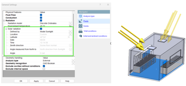 Setting up sunlight in the general settings
A transient analysis can be setup to simulate the sun shining on the building over the course of a few hours. The results can be displayed with incident and radiant flux plots. Additionally, surface contour plots can be created to show the flux on the outer walls of the building.
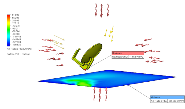
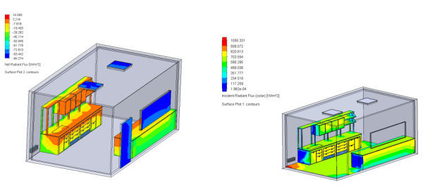 Solar flux plots from the radiation simulation