Summary
Learn how to precisely locate structural members by customizing weldment profile insertion points.
SOLIDWORKS CAD software provides a wealth of functionality including the ability to customize. One of the features you’ll benefit from customizing are the weldment profiles included with SOLIDWORKS. Adding additional sizes and shapes to your library often comes to mind, but don’t forget the importance of the insertion point.
Your designs may require specific points for locating the profiles in your model. It’s easy to add multiple points to the profile sketches to give several options for locating the profiles and therefore the structural members. We’ll start with an introduction/refresher on weldments and then show how to locate the Structural Members in SOLIDWORKS Weldments, edit the profiles, and add points.
What are SOLIDWORKS Weldments?
SOLIDWORKS includes a library of standard structural members, such as tubes, pipes, c-channels, beams, angles, and unistrut. By creating a sketch that represents the skeleton of a frame, these structural members can then be inserted onto the sketched framework. From there, various end treatments can be applied to the structural members to make the appropriate connections. The result is a multibody part known as a Weldment.
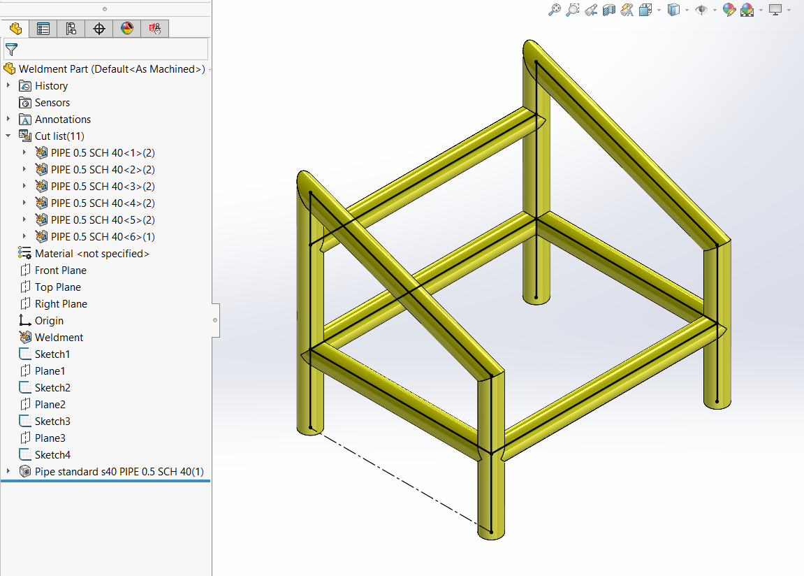
The FeatureManager Design Tree will contain a Weldment feature which indicates the weldment environment is enabled and a Cut List of the structural members. 2D or 3D Sketches can be used to build the basic framework of the weldment. Below is a weldment composed of ½” Schedule 40 Pipe.
SOLIDWORKS Weldments Feature
Locate Profile
Weldment profiles are basically the 2D sketches that will be extruded or swept along the segments of the skeleton sketch. When inserting a structural member, there is a button in the property manager called Locate Profile. This allows a point or endpoint in the weldment profile sketch to be referenced as the insertion point for the structural member. Otherwise, the origin of the profile sketch will be used as the insertion point. The weldment profiles that have two lines of symmetry, such as tubes, pipes, and I-Beams, have the origin in the center of the profile. This makes it so the skeleton sketch segments are the centerlines of those structural members, by default. Other profiles, such as Angles and C-Channels, have the origin at a corner or other point of the profile.
To use the Locate Profile option, first select a segment for the path of the structural member and a preview will be shown. Then, click the Locate Profile button and select a point in the profile sketch to locate it relative to the path segment. This is illustrated in the image below using a wide flange beam. Notice, the sketch point does not need to be on the contour of the profile.
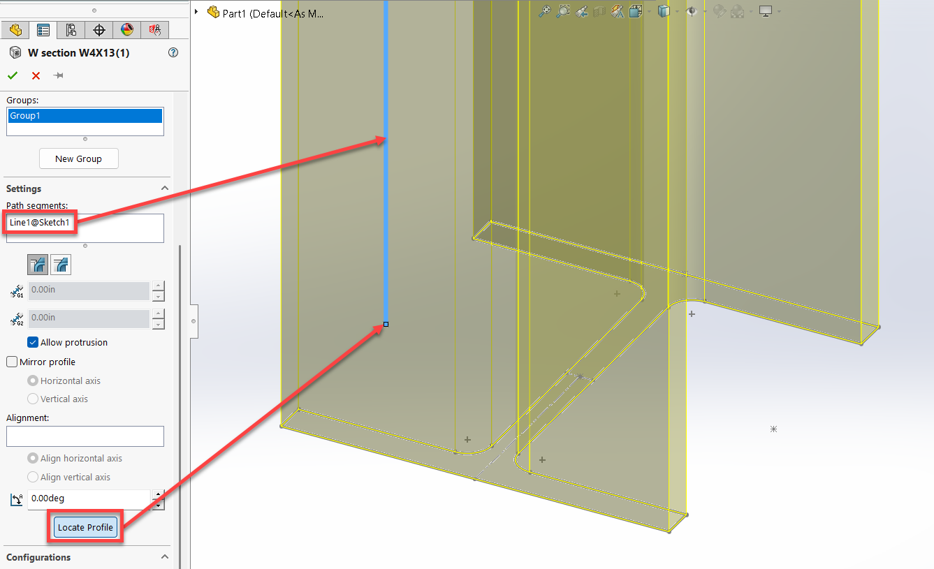
Locate Weldment Profile
File Location for Weldment Profiles
Weldment Profiles are created by simply saving a sketch as a library feature part (*.sldlfp) and storing it in the designated Weldment Profiles location. By default, Weldment Profiles are located in the folder,
C:\Program Files\SOLIDWORKS Corp\SOLIDWORKS\data\weldment profiles.
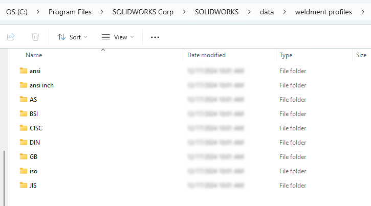
Weldment Profile Folder Location
SOLIDWORKS provides several weldment profiles organized by standard, i.e. ANSI, AS, BSI, CISC, DIN, GB, ISO, JIS, and Unistrut. All of these, except Unistrut, are automatically loaded in the default location when installing SOLIDWORKS. This set of profiles are configuration based, however the number of configurations/sizes are limited.
Fortunately, another set of files for the same types of profiles, as well as Unistrut profiles, can be downloaded from the Design Library Task Pane > SOLIDWORKS Content >Weldments folder
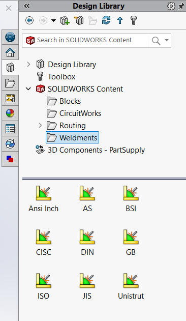
Weldment Profile Library
Although the downloadable profiles have more sizes to choose from, they are single configuration files unlike the automatically installed configured profiles. This is something to consider when deciding how to manage your library.
You can change the path or add additional folders for weldment profiles in SOLIDWORKS > Options > System Options > File Locations > Show folders for: Weldment Profiles.
Editing Weldment Profiles
Recall that a weldment profile can be positioned based on a point in the profile sketch. If a weldment profile does not have the desired insertion point, then it’s just a matter of editing the sketch and adding the necessary point.
Suppose the design intent for a weldment of pipes calls for the distance between the pipes to be measured from Outside to Outside rather than On-Center.
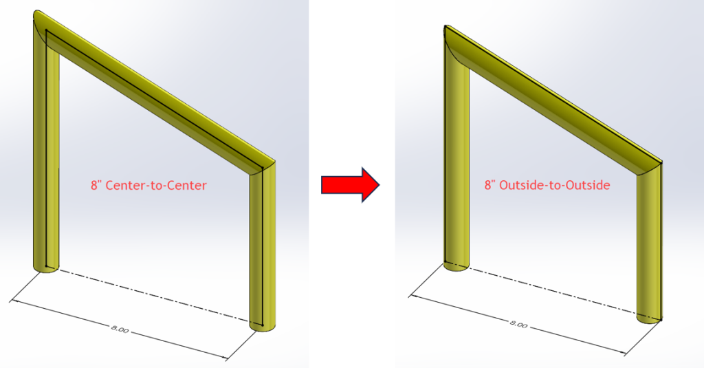
Measured from Outside to Outside rather than On-Center
The profile being used in this example is ½” Schedule 40 pipe from the file, pipe standard s40.sldlfp, which is one of the default profiles included with SOLIDWORKS. The sketch in this file only has one point, the centerpoint. We’ll add four more points on the quadrants of the outer circle.
Since we are customizing a library, it is good practice to copy the folder to a location outside of any SOLIDWORKS directory. This keeps the default files intact, should they ever need to be restored. It also avoids the possibility of unintentionally deleting customized files during an uninstall of SOLIDWORKS.
After the files are copied, uncheck the Read-only option on the copied folders to be able to modify them
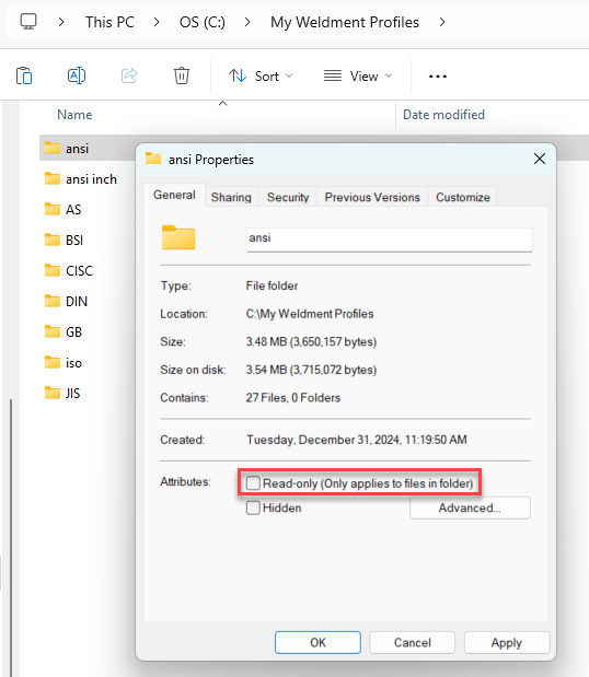
Uncheck the Read-only option on the copied folders to be able to modify them
Make sure to add the new folder path in SOLIDWORKS > Options > System Options > File Locations > Show folders for: Weldment Profiles.
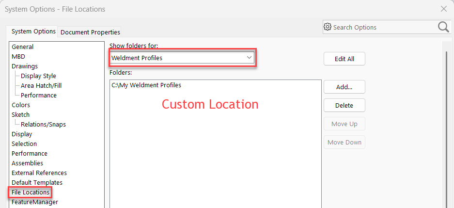
Add the new folder path
Using the Segment Command to Add Points
Now, the fun part. As mentioned above, weldment profiles are simply 2D sketches saved as Library Feature Part files (*.sldlfp). Open the profile for the pipe and edit the sketch to add 4 points on each quadrant of the outer circle. An easy way to add multiple sketch points is to use the Segment command. This command is in the Tools menu > Sketch Tools flyout menu. Quick Tip: Press the S key to bring up the contextual Shortcut Toolbar in the graphics area. Then, search for the Segment command instead. Clicking the + icon will add the command button to the Shortcut Bar for future use.
Select the outer circle and enter 4 for the number of sketch points. These points will then be selectable when using Locate Profile in the Structural Member Property Manager.
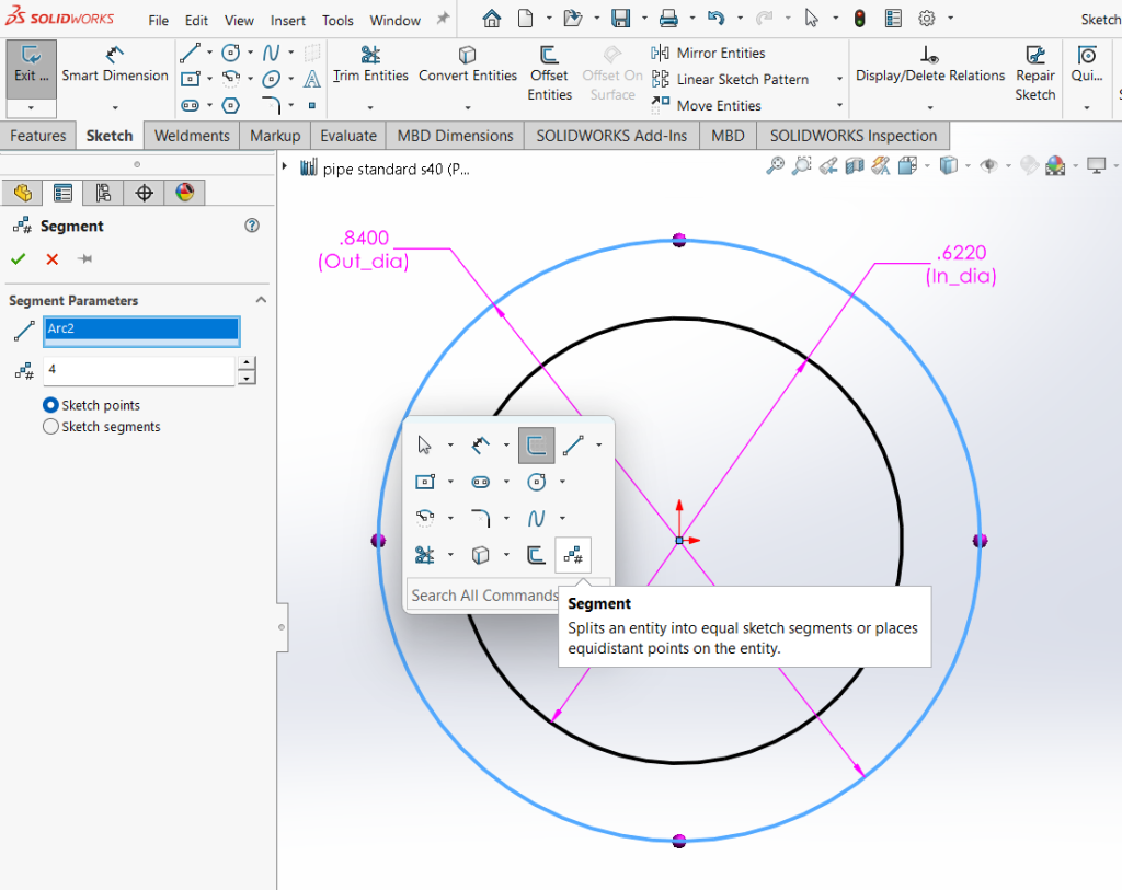
Using the Segment Command to Add Points
Take it further by sketching a rectangle around the large circle and constraining it so the circle is inscribed in a square. The four corners of the square will provide additional points for locating the profile in a weldment part.
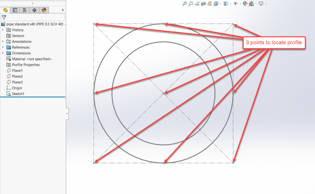
Constraining a circle in a square
You can read our article on speeding up the design process with SOLIDWORKS Instant 3D