Summary
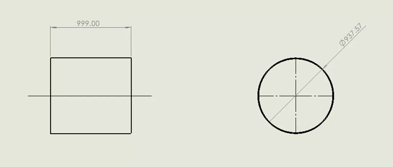
Centerlines may appear solid due to new layer behavior. Adjusting settings restores dashed display.
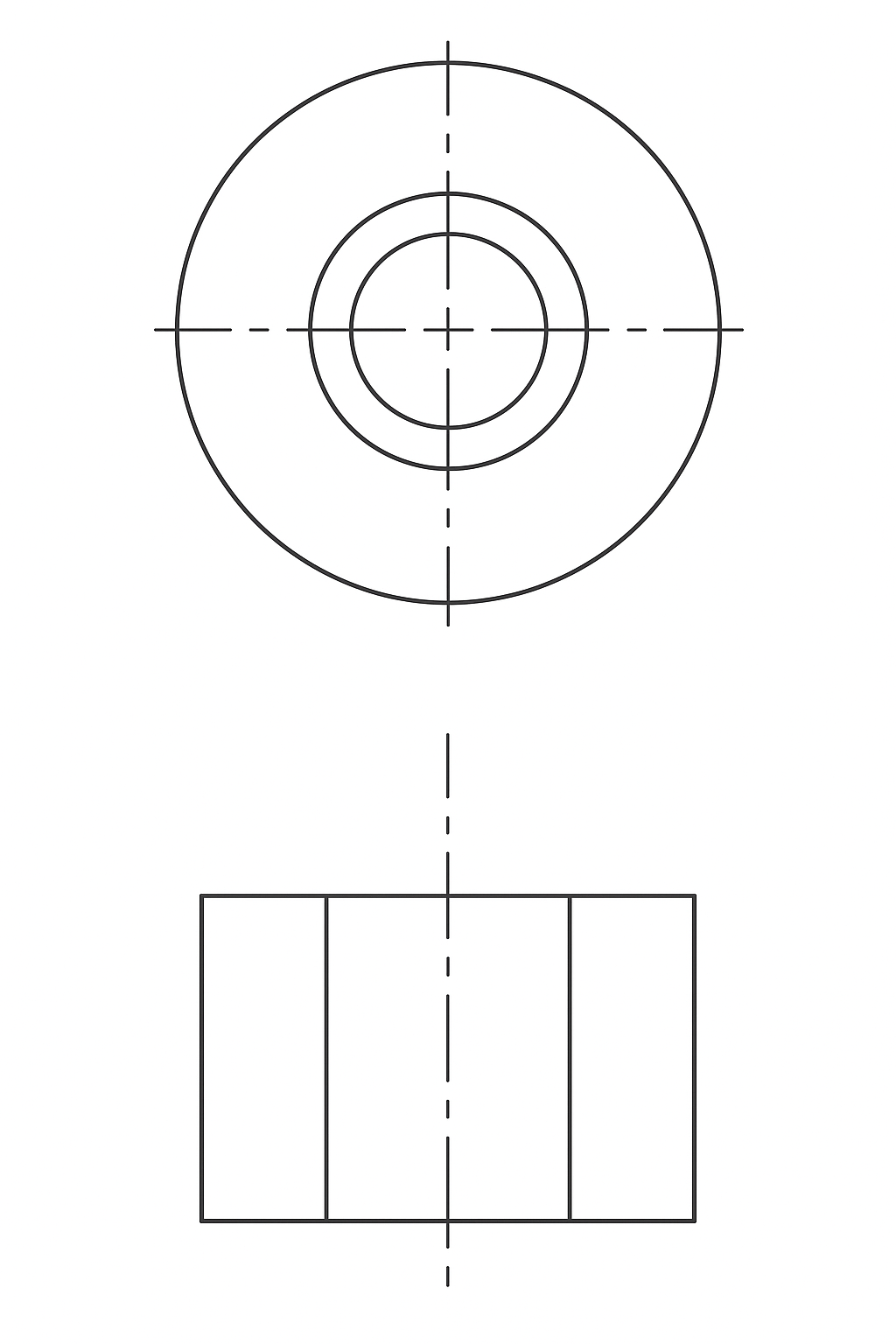
Centerlines are dashed lines that can be inserted into a drawing by holding CTRL and clicking the edges/sides of the cylinder. You will see a dashed line has been inserted into the view. Similarly, you can insert a center mark by selecting the edge of a hole and then selecting the Center Mark command. These lines are quite useful for dimensioning and annotating drawings, and, as a result, they have become standardized as a fundamental part of GD&T. But if you have SOLIDWORKS 2025 SP3 installed, you may have noticed some changes in the behavior of centerlines and have asked yourself, "Why are centerlines coming in as a solid line? What has changed, and how can I stop this?".
 SOLIDWORKS Drawing File
Let’s Check the SOLIDWORKS Knowledge Base
As outlined in QA00000424556 in the SOLIDWORKS Knowledge Base, SOLIDWORKS has actually expanded the functionality and control of centerlines to support the use of layers.
Layers are commonly used to control the color of annotations. A prime example of this is with “Red Line Drawings”. Adding a layer, set to red, allows an engineer to quickly make all his edits to a drawing that can be shown, hidden, or modified all at the same time. Layers can also control line weight and style.
 SOLIDWORKS Drawing Layers
I often compare SOLIDWORKS to a fighter jet - it gives us a high degree of control, but this high degree of control adds complexity that needs to be managed.
Control Centerlines with Layers
The first step is to turn on the Layers toolbar. The quickest way to have your centerlines come in as dashed is to start working in the Per Standard layer option.
 Standard Layer Option
In previous versions of SOLIDWORKS, if you moved a centerline to another layer (perhaps to change its color, like in our red line example), the centerline would change color, but it wouldn’t obey the layer’s line style. But in SOLIDWORKS 2025 SP3, it will. So, if you are unknowingly working in the “format” layer, this causes your lines to come in as solid. I suggest the Per Standard layer because this is not actually a layer at all. Under this setting, the line follows the standards that are set in the document properties of your template.
This brings us to the second solution. A great option is to add a layer to your organization's template titled “centerlines/marks”. This solution requires some extra steps, but it provides consistent results across your team.
 SOLIDWORKS Layer Option
We can then define how all the centerlines and marks look (if you want your centerlines or marks to look different, add a layer for each). This means that if you ever need to change the way your centerlines look in the future, you can change all of them in the entire drawing just by changing the layer.
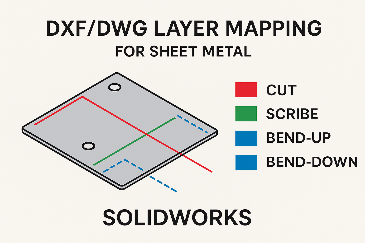
Additionally, if you ever need to hide the centerlines to export the drawing as a DXF or DWG (some lasers or CNC machines may make cuts on centerlines), you can hide the center mark for all the holes in your drawing with a few easy clicks.
 Layer Option File
If you have any gaps in your knowledge regarding the ‘SOLIDWORKS DXF/DWG Layer Mapping Guide,’ then this article is just for you.