Summary
Learn how to map entities by type to specific layers for sheet metal DXF/DWG exports.
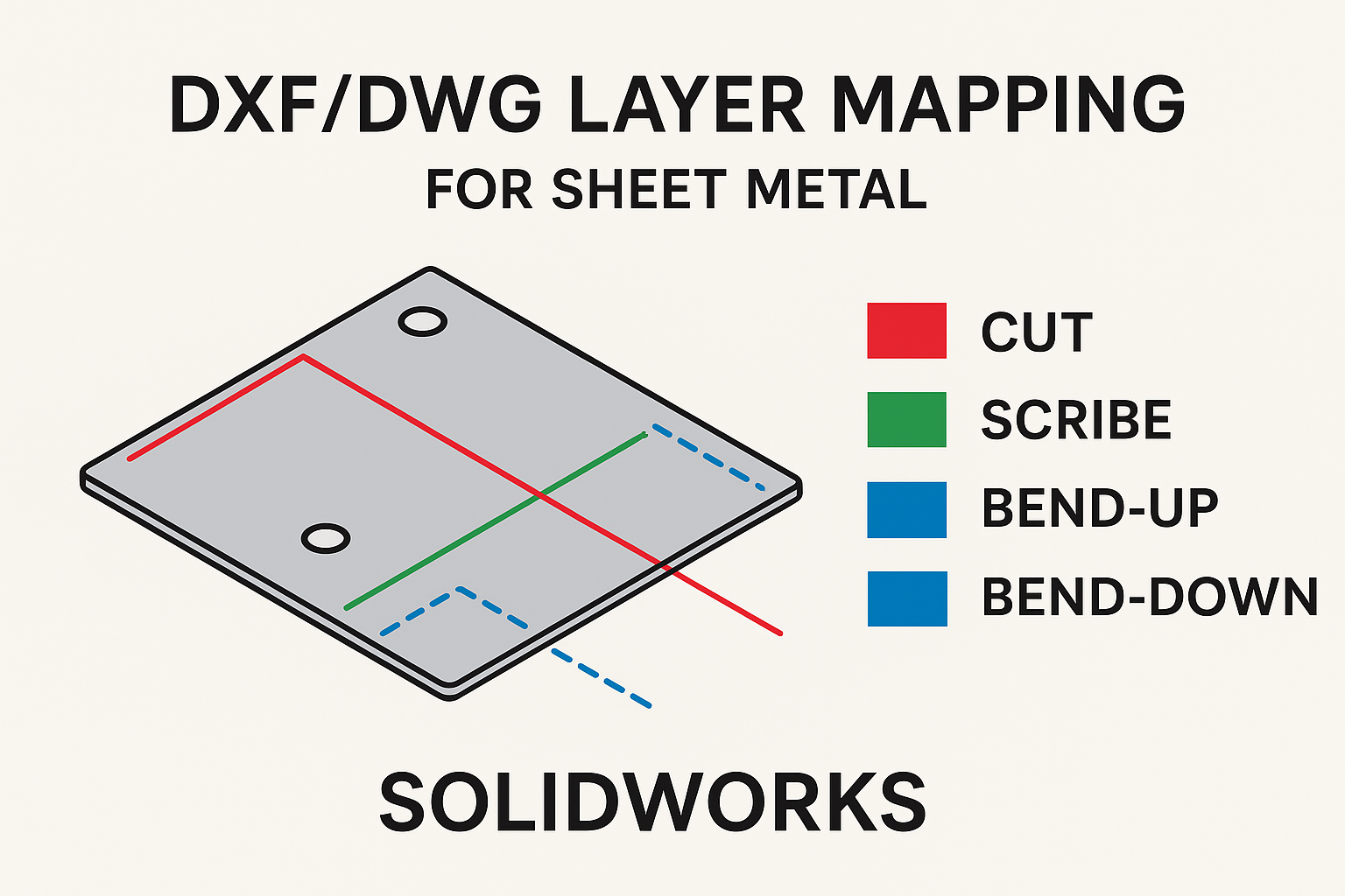
Mapping entities by type to a specific color and line format layers is a useful tool when converting SOLIDWORKS files to 2D drawing exchange formats like DXF or DWG. Groups of entities can be assigned to specific layers. Named layers are commonly used by CNC sheet metal cutting post-processing software to assign processing methods automatically. For example, post-processing software can be configured to always scribe/etch entities assigned to a DXF layer named SCRIBE. With a little bit of up-front configuring, SOLIDWORKS makes it easy to map entities to specific layers repeatedly when converting from SOLIDWORKS Sheet Metal to DXF or DWG files.
 Sheet Metal to DXF or DWG files.
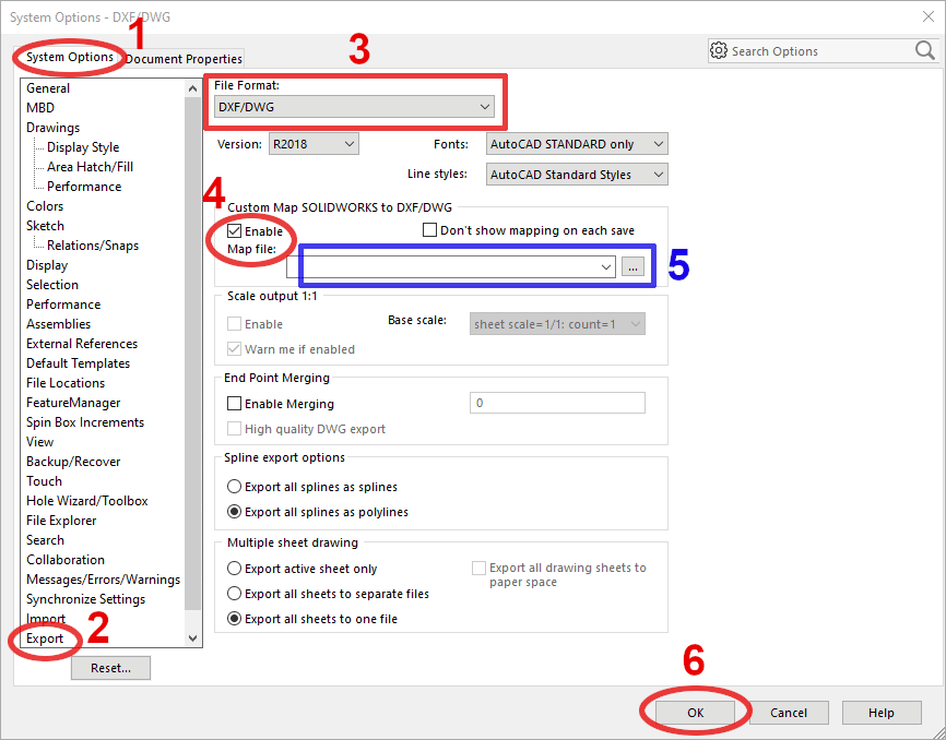
1. Select Tools > Options > System Options.
2. Select the Export category.
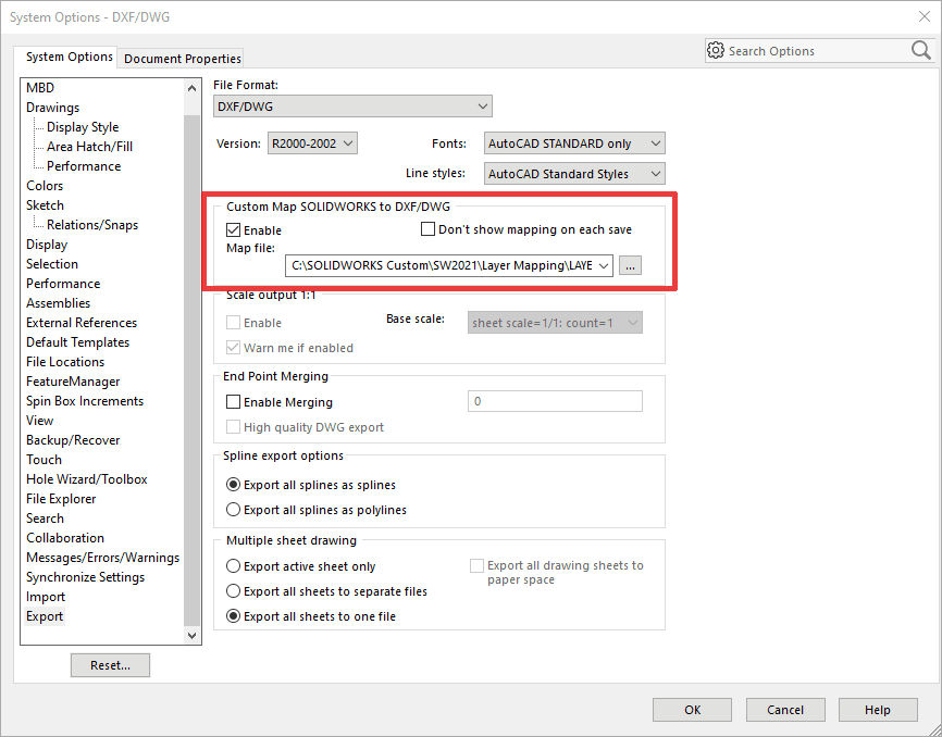
3. From the File Format dropdown list, select DXF/DWG.
4. For Custom Map SOLIDWORKS to DXF/DWG, turn on Enable Map file.
5. The file location will populate automatically the first time a mapping file is created and saved. This location can also be changed on-the-fly for different DXF/DWG requirements.
6. Click OK to save the options changes.
 System Options- DWG-DXF
For this example:
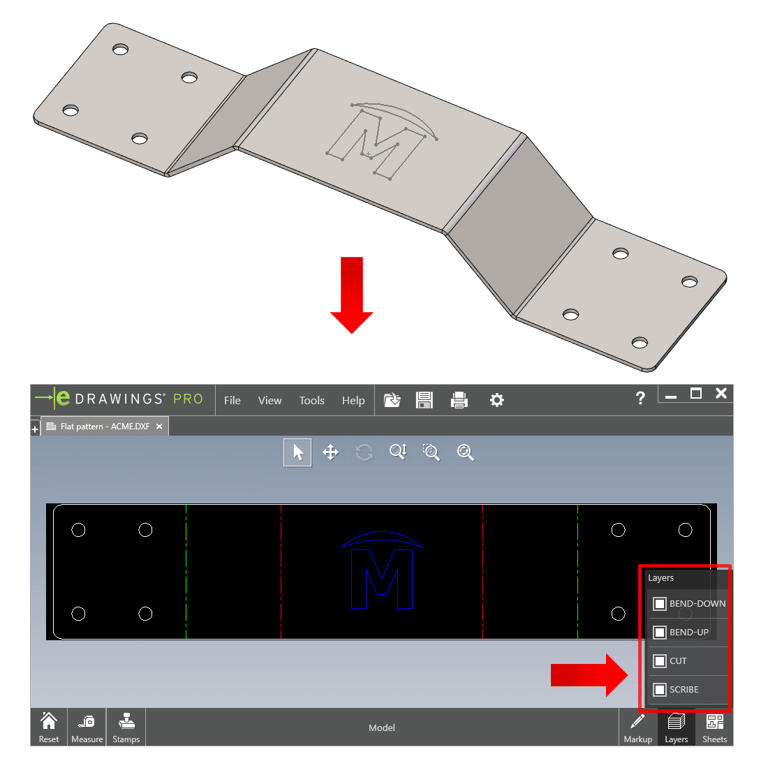
Geometry = the edges of all visible geometry (perimeter and holes)
Bend Lines = all sheet metal bends
Sketches = the visible sketch on the center of the part (sketches must be visible to map using Sketches)
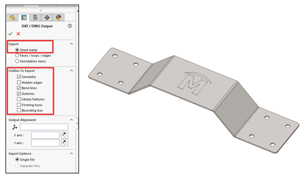 DXF/DWG Output
Click the Green Checkmark to accept the options.
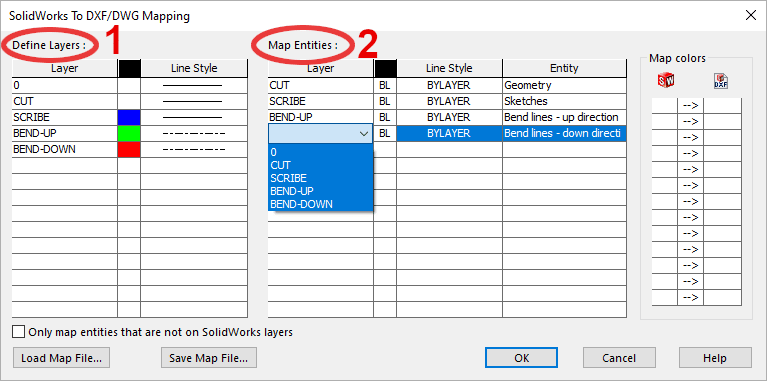
The Map Entities section allows you to map SOLIDWORKS Entities To Export to the DXF/DWG Define Layers created in the left column.
For this example, we assigned Geometry to the CUT layer, Sketches to the SCRIBE layer, and the Bend lines to their associated BEND-UP and BEND-DOWN layers. To map both bend directions to the same layer, simply select the same Define Layer from the Layer dropdown list (center column).
Once satisfied with your selections click OK to create the DXF/DWG with the mapped layers.
 DXF/DWG Mapping
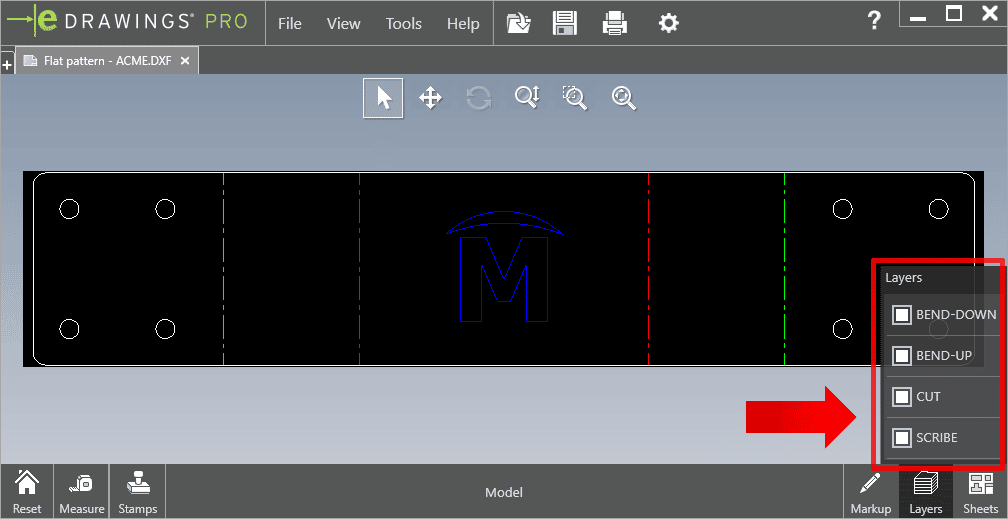
The DXF/DWG is created with the correct layer names, colors, and line styles.
 Mapping eDrawings File
If you will always use the same mapping file and no longer want to see the SOLIDWORKS to DXF/DWG Mapping dialog which displays the layer configuration, then activate the option Don’t show mapping on each save. SOLIDWORKS will then use the specified mapping file to map all entities to the Define Layers.
 System Options SOLIDWORKS
If you don't have enough knowledge about "Adding Sheet Metal Properties to Drawings in SOLIDWORKS", make sure to read this blog post before moving on